Imagine comparing two shift records that both say “pressure normal.” One refers to the pump discharge with a bypass open; the other was taken at the spray header. Neither number need be wrong, but they aren’t describing the same thing. That is the difficulty with using PCB spray pressure to explain a spraying fault without also knowing where the liquid went and how the machine was running.
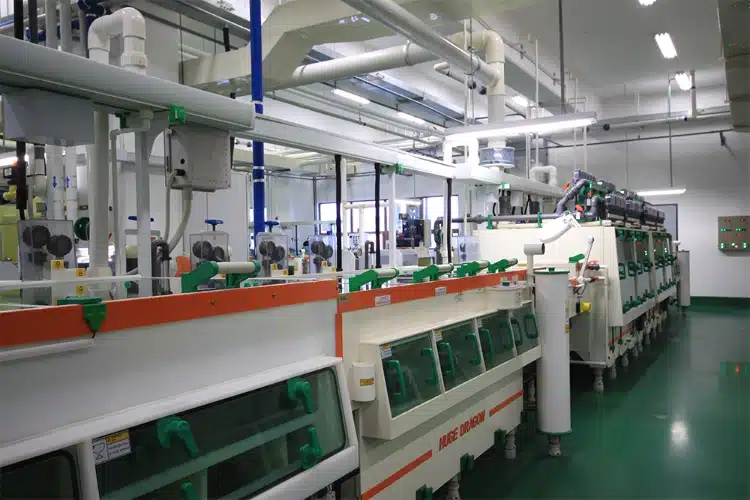
The connection with today’s manufacturing-data discussion is close to the shop floor. The Global Electronics Association, writing about AI in September 2026, calls attention to the quality of the data and the people interpreting it. Its September 2026 discussion of AI adoption in electronics manufacturing offers the wider context. Here, the immediate question is whether another technician could reproduce a recorded measurement.
Give every reading a location and a condition
A circuit drawing helps resolve the first ambiguity. The pump-outlet gauge and the spray-header gauge occupy different places, possibly with a filter, several valves, pipework, and a change in height between them. Calling both readings “spray pressure” loses that distinction. Put the instrument identity and its connection point on the drawing before making a comparison across shifts or after maintenance.
The flow meter can introduce a second ambiguity. Suppose liquid leaving the meter divides, with some feeding the spray bank and some going elsewhere. The meter sees both. Even an unchanged total reading then leaves an unanswered question about the amount reaching the bank. Trace any bypass and other open branches on the drawing before assigning that reading to the nozzles under investigation.
The machine recipe belongs with these observations. It identifies the liquid and its temperature, with concentration where relevant, as well as pump setting, valves, active nozzles, and line speed. Comparing different recipes could explain an apparent drift without any failed part. For a supplier looking at replacement PCB equipment pressure gauges, the description is useful in another way: it identifies the medium and the connection for which range and suitability must be considered.
Building a usable pressure and flow baseline
The word “normal” on an old sheet is not much of a reference unless the process was actually verified. Choose a run after the approved cleaning and inspection, then note the nozzle set and positions, header layout, filter condition, and instrument status. Someone returning to that record needs to know which arrangement produced it.
Take the header pressure and flow together when the line reaches its normal operating condition. Where approved taps exist on both sides of the filter, subtract outlet pressure from inlet pressure using the same units. That is the filter pressure difference at the recorded flow. A later reading made with another liquid or flow needs that difference explained before it is attributed to the cartridge.
The spray result belongs in the reference as well. Spraying Systems’ nozzle-wear guidance starts with new-nozzle performance and follows flow, manifold pressure, alignment, and application results. A record of acceptable spraying is the link between the instrument numbers and the board being processed.
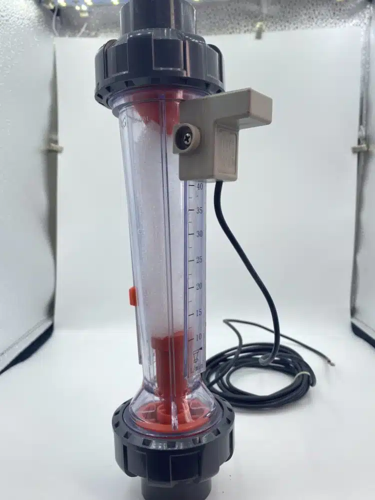
For local observation, Qixingyuan supplies PVC flow meters. Ask which liquid the scale represents and what installation orientation it requires, as well as confirming range and wetted materials. A water calibration leaves a question to resolve when the actual liquid is a different chemical solution; it isn’t permission to use the scale without qualification.
Read pressure and flow as a pair
After the instruments and operating conditions have been checked, paired changes can help decide where to inspect. The table assumes the same recipe, active branches, and measurement locations. Its entries are possibilities to investigate, rather than diagnoses made from the readings alone.
| Observed change | Possible explanation | Inspection focus |
| Header pressure down; branch flow down | Less supply or more upstream resistance | Liquid level, pump setting, valves, filter |
| Pressure rises before a part; flow drops after it | Resistance between the two locations | Tap positions and the intervening part |
| Header pressure steady; branch flow up | Different nozzles, bypass, leak, outlet wear | Nozzle identification, routing, connections, nozzle output |
| Total readings steady; one zone uneven | A local spray problem | Blockage, orientation, damage, board-plane coverage |
Pump controls are one reason to resist a universal rule about nozzle wear. Enlarged outlets can change flow and distribution, while a regulated system continues holding its pressure setpoint. Another installation may respond differently. Filter pressure difference also needs comparable flow and liquid conditions before an increase can be attributed to blockage.
Investigate an uneven zone without losing the evidence
Map a recurring strip onto the machine layout: is it associated with the bank above the board or below it, and where is it relative to travel? Successive panels help show whether the position really repeats. Take a copy of the pressure, flow, temperature, and open-branch conditions while they still describe the fault. Chemistry and transport remain inside the approved process window throughout.
Observe the machine’s isolation and chemical-handling procedure before inspecting components. A nozzle comparison includes the identifier, installed orientation, seal, and pipe connection, with the drawing or approved spare as the reference. There are different cores and spray forms in Qixingyuan’s spray nozzle range, so fitting the holder is only part of the match. Clean by the permitted method; a hard tool forced through an outlet can damage it.
The test after correction should still answer a question. Replacing nozzles and the filter while also changing pump speed may improve the spray, but it won’t tell you which action helped. Where the approved test permits, make one identified change and retain its retest result before moving to another. That gives the maintenance history an explanation for the improvement.
Make the record useful for maintenance planning
Identify the event by time and module. Its entry needs the recipe, liquid condition, instrument locations, readings, spray observations, and intervention. Distinguish what was suspected from what was found. An inspection that confirms a restriction provides different evidence from a note proposing one as a possible cause.
Paper records can do this job. Adding remote monitoring later raises another set of purchasing questions, since a dial or a visual meter doesn’t necessarily have anything a controller can read. Specify the required output and the equipment that will acquire it, including sampling and installation work. Keep the old measurement locations and units where possible, so a change of recording method doesn’t also become an unexplained break in the history.
A threshold for investigation should come from the machine supplier’s requirements and the plant’s verified process window. Crossing it may justify an inspection. It doesn’t, on its own, estimate remaining life. Predictive maintenance needs the history of readings connected to confirmed findings and outcomes before a replacement decision can rest on it.
Order the replacement around the confirmed finding
An inquiry needs enough detail to identify both the part and its working conditions: module, process liquid and temperature, instrument range, connections, dimensions, photographs, and readings before and after the work. For a nozzle, add its approved core identifier, spray form, count, and header drawing. For an instrument, state the measurement point and calibration requirements.
Qixingyuan supplies spray and measurement spares for wet-process equipment. Send the inquiry through its technical inquiry with the inspection information, so the part can be considered in its installation. That information also explains why purchasing is seeking a replacement and whether a setting or instrument problem has already been investigated.
Abschluss
When reviewing PCB spray pressure, read the entry as a description of a run: where the measurement came from, how the line was set, and what flow and spraying result accompanied it. A verified reference gives the comparison a starting point. Confirmed inspection findings explain what the later changes meant. Those are useful records to have whether they came from a notebook or an electronic system.
Frequently asked questions
Can normal PCB spray pressure rule out a blocked nozzle?
No. One restricted nozzle may barely alter a main gauge reading. Inspect the affected spray pattern and check nozzle output by the approved method, then consider the observations alongside the wider circuit readings.
Should pressure be increased when branch flow falls?
Not before checking the reason. A different recipe, liquid level, valve position, restriction, or instrument condition may explain the fall. Raising pressure could leave that cause unresolved or take the line outside its approved settings.
Does a flow meter make the line ready for predictive maintenance?
The meter contributes a reading. That reading still needs an appropriate collection method, consistent operating conditions, reliable records, and confirmed fault information behind it. Installing a visual meter alone doesn’t provide those things.