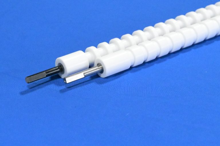
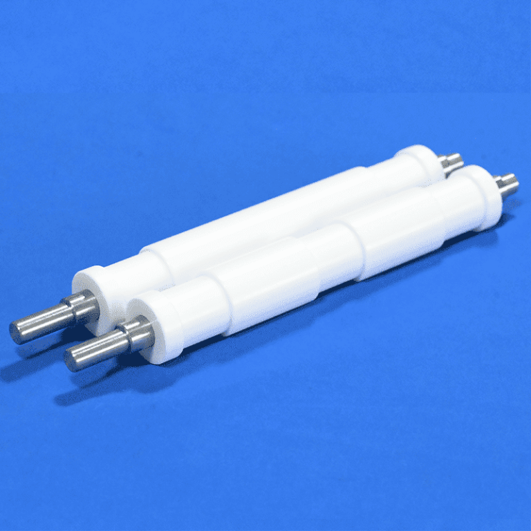
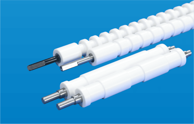
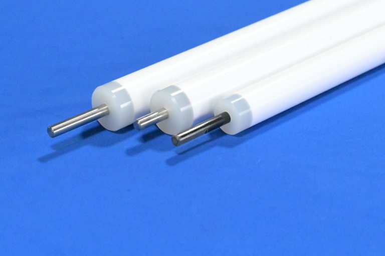
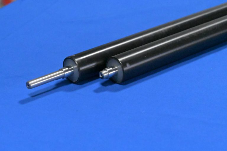
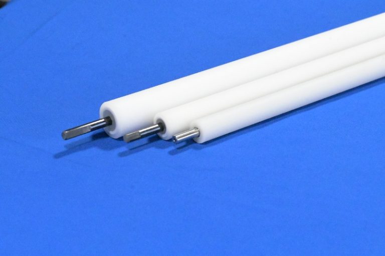
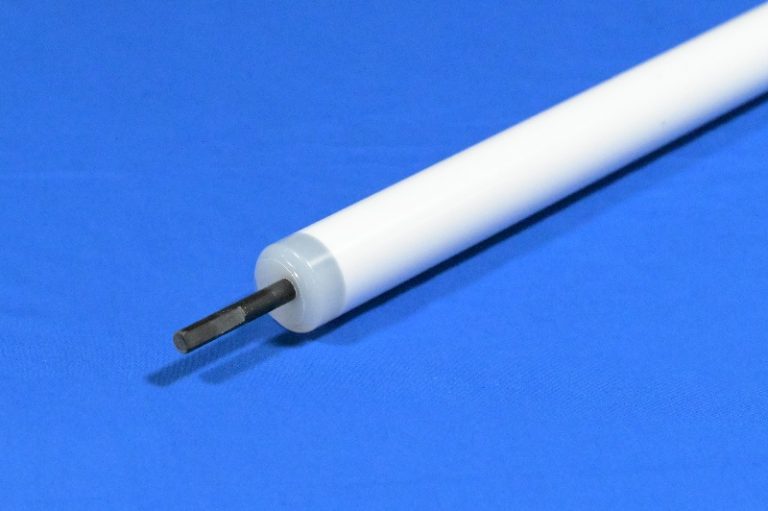
The PP conveyor roller with groove is designed for transmission and board conveying positions in PCB equipment. Its grooved profile is a key part of the roller specification and must match the corresponding drive or contact arrangement. Correct roller dimensions and groove geometry help the assembly fit the machine and maintain the intended board movement.
Model 6-3 is available in white with acid and alkali resistance, a specified hardness of 90 to 105, heat resistance of 100 degrees C, and radial runout of 0.15 mm. Size can be customized for the required working width and installation space. The groove profile and mounting details should be confirmed against the equipment drawing or an existing sample.
| Item | Specification |
| Product Number | 6-3 |
| Product Name | PP conveyor roller with groove |
| Primary Application | Transmission in PCB equipment |
| Roller Profile | Grooved design |
| 내화학성 | Acid and alkali resistance |
| 경도 | 90 to 105 |
| Color | White |
| 내열성 | 100 degrees C |
| Radial Runout | 0.15 mm |
| Size | Customizable |
– Grooved roller profile supports the specified transmission arrangement. Groove geometry must match the mating component and the equipment drawing.
– Acid and alkali resistance supports use where the roller is exposed to process solutions or cleaning liquids.
– The specified radial runout of 0.15 mm provides a reference for rotational accuracy during equipment matching and inspection.
– Heat resistance of 100 degrees C provides a temperature reference for selection. Confirm suitability for the intended continuous duty.
– Custom dimensions allow the roller to fit different working widths and mounting positions.
– The white surface makes visible deposits and damage easier to identify during routine inspection.
A conveyor roller supports and moves the PCB through the machine. Roller diameter and drive speed affect board travel, while the working length determines the available support width. At a transmission position, the groove profile also needs to match the drive interface. An incorrect groove position, depth, or shape can prevent proper engagement even when the overall roller dimensions appear correct.
In wet-process equipment, deposits and process liquid can affect roller contact and rotation. Where the machine uses the roller as part of its liquid-control arrangement, correct contact and alignment can also help limit unwanted liquid movement. This function depends on the surrounding equipment design, board thickness, and mating components.
– Grooved transmission positions in PCB conveyor systems
– Board conveying and transfer sections in PCB machinery
– Wet-process conveyor positions exposed to acidic or alkaline solutions
– Replacement rollers for existing grooved transmission assemblies
– Customized conveyor assemblies for PCB equipment manufacturers
Specify the number of grooves, groove width, groove depth, profile, and distance from the roller end. When several grooves are present, include their spacing and the reference point used for measurement. A section view is useful because rollers with similar outside diameters may have different groove shapes.
Identify the component that engages with the groove and provide its dimensions or part drawing. If the design uses a belt, include its cross section and installation position. The final groove specification should follow the approved machine design so the replacement roller works with the existing drive arrangement.
Roller size can be customized to the installation. Provide the outside diameter, working-face length, overall length, shaft or bore dimensions, mounting positions, and groove details. Include any drive features or shaft-end geometry shown on the original part.
For a replacement order, photographs of the complete roller, each end, and the groove profile help identify the assembly. A drawing or sample provides a clearer reference for dimensions that are difficult to measure in place. Confirm the roller construction, shaft material, groove profile, surface requirements, and tolerances before production.
Confirm the groove profile and mounting dimensions first. Then review board thickness, conveying speed, load, contact pressure, chemical exposure, and operating temperature. Check that the roller works with adjacent rollers, bearings, and the existing drive component throughout the required travel path.
The specified hardness range is 90 to 105. Agree the test method and acceptance requirement with the supplier. Acid and alkali resistance should be assessed under the actual solution concentration, temperature, and exposure duration. Provide the continuous operating temperature when requesting confirmation of the listed heat resistance.
– Isolate the equipment according to its maintenance procedure before removing or fitting the roller.
– Check roller dimensions and groove geometry against the approved drawing or original assembly.
– Clean the grooves and mounting area to remove deposits that could interfere with fit or rotation.
– Fit the assembly without bending the shaft, forcing the drive component, or damaging the groove edges.
– Check alignment, free rotation, clearance, and engagement with the mating component.
– Set contact pressure and any belt tension according to the equipment manufacturer’s procedure.
– Inspect for groove wear, cracks, deposits, loose mounting parts, and abnormal vibration.
– Use compatible cleaning methods and replace the roller when damage affects drive engagement or board movement.
Use an approved drawing or confirmed sample as the order reference. Include outside diameter, working length, shaft or bore dimensions, groove geometry, hardness test method, and the radial runout acceptance requirement. Groove measurements deserve particular attention because a small mismatch may affect the drive connection.
Qixingyuan Machinery supplies accessories for PCB equipment. Send the roller drawing, sample information, and operating conditions to discuss dimensional customization and product selection. Clear groove and mounting details help define the required replacement assembly and prepare an accurate quotation.
Confirm packaging that protects the working surface, groove edges, and projecting ends against impact and bending. Discuss packing dimensions, quantity, destination, and delivery requirements when requesting a quotation. Keep the roller free from deposits and damage before installation.
– Model 6-3, equipment model, and installation position
– Outside diameter, working-face length, and overall length
– Groove number, profile, width, depth, spacing, and location
– Shaft or bore dimensions and mounting details
– Drawing, sample, or photographs of the roller and mating component
– Process liquid, concentration, temperature, and exposure duration
– Conveying speed, board thickness, load, and contact requirements
– Quantity, delivery destination, and requested delivery date
What is this grooved PP roller used for?
Model 6-3 is intended for transmission and conveying positions in PCB equipment. The grooved profile must be matched to the machine’s drive or contact arrangement.
What groove dimensions are needed for a replacement?
Provide the groove number, width, depth, profile, spacing, and position relative to the roller end. Include a drawing or sample when possible.
Can the roller size be customized?
Yes. Provide the roller dimensions, mounting details, groove geometry, and equipment requirements for confirmation.
What are the heat resistance and radial runout values?
The specified heat resistance is 100 degrees C and radial runout is 0.15 mm. Confirm the duty conditions and inspection requirements when ordering.
What is the hardness?
The specified range is 90 to 105. Agree the hardness test method and acceptance criteria with the supplier.
Is the roller suitable for acids and alkalis?
The roller is specified as acid and alkali resistant. Provide the actual solution, concentration, temperature, and exposure duration so suitability can be reviewed.
고정밀, 고성능 PCB 장비 액세서리를 제공하여 전 세계 전자 제조 산업이 효율적인 생산을 달성할 수 있도록 지원합니다.