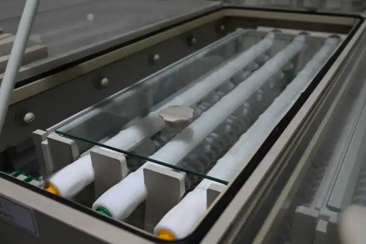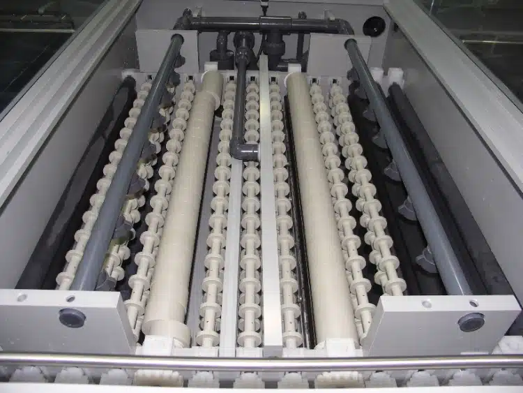
A maintenance calendar can tell you when to look at a wheel. It cannot tell you what happened at each shaft position. Inside an abrasive cleaning section, media does not always reach every wheel in the same way. Splash direction, board loading, alignment, cleaning practice, and the condition of the shaft seat can all change the wear pattern.
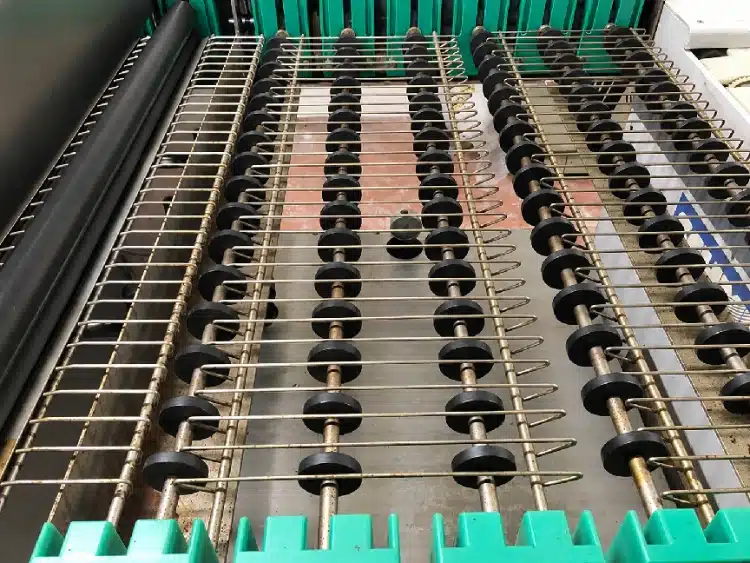
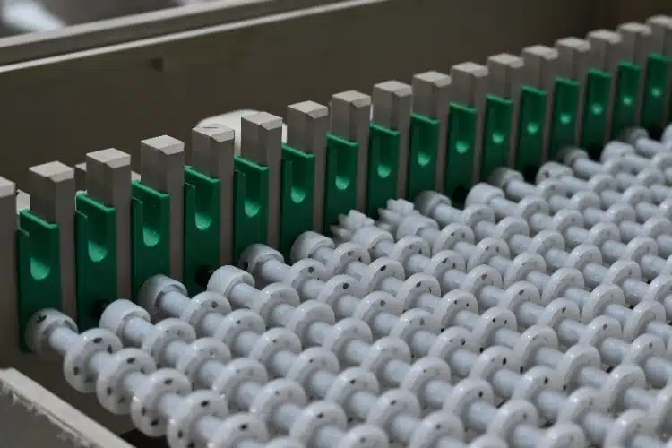
That is why sandblasting machine wheel discs are better inspected as a group. If the old parts are removed and mixed together, useful evidence disappears. A simple position map made before disassembly often says more than a row of worn black wheels on a bench.
The timing matters. In October 2026, SEMI’s forecast projected an 11.8% rise in global silicon wafer shipments for the year, with further record highs expected through 2029. That forecast is about semiconductor wafers, not PCB cleaning-wheel life. Still, it reflects the production pressure found across electronics manufacturing. When schedules tighten, maintenance teams need evidence they can act on before a transport problem becomes a stoppage.
Photograph the module before touching the shaft
Start with the installed assembly. Number each wheel position, then mark the drive side, operator side, board-travel direction, and the side where media enters. Take one photograph wide enough to show the entire module and closer views of any position that already looks different.
The purpose is not to create a perfect inspection report. It is to keep position attached to condition. Once the wheels are loose, a technician may remember that one was badly worn but not whether it came from the media-entry end, the center of the shaft, or the discharge side.
Record the details that are easy to see: a wider contact band, a polished edge, a flat spot, pitting, cuts, residue, or sideways movement. Also note whether neighboring wheels look similar. Matching wear across several positions can be normal for that particular setup. One wheel that looks markedly different deserves a closer look at local exposure, alignment, support, and retention.
Do not treat the map as proof of root cause. It is a way to narrow the next inspection. A worn wheel at one location may be the cause of poor transport, the result of a shaft-seat problem, or simply the most visible part of a larger assembly issue.
Read the wheel face and bore separately
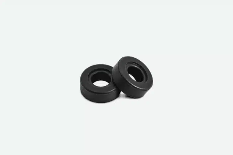
Face wear and bore wear answer different questions. The face shows how the wheel has been contacting the board or responding to the abrasive environment. The bore shows how securely the wheel has followed the shaft.
On the face, look for flat areas, grooves, pits, edge loss, and a contact band that is wider on one side. A single mark is not automatically a failure. What matters is whether it changes the intended profile or appears together with slip, skew, vibration, or an unwanted contact mark on the panel.
Then inspect the bore. One-sided polishing, an oval shape, looseness, or cracking suggests that the wheel may have moved relative to the shaft. At that point, fitting another wheel without checking the mating surface risks repeating the same damage.
The surrounding parts deserve the same attention. Check the shaft seat, spacers, locking features, supports, and axial location using the equipment owner’s procedure. A wheel can appear serviceable in your hand and still behave poorly when the assembly allows it to shift under load.
Qixingyuan’s Sandblasting Machine Wheel Disc page lists NBR wheel discs for abrasive cleaning applications. It also describes P001, P002, and P003 series options, including bore and width choices and references to 10 mm and 12 mm shafts. Those are product-series options rather than a universal fit chart. The replacement still has to match the shaft and support arrangement on the actual machine.
Let uneven wear guide the next question
If one position is wearing faster, ask what is different there before asking for a harder wheel. Is the abrasive stream concentrated on that zone? Does rinse carry residue toward one end? Has a guard, nozzle, or support moved? Is the board loading different at that point? Did the cleaning routine or process liquid change before the wear accelerated?
These questions matter because wheel color tells very little. Two black elastomer parts may use different formulations or hardness levels. A harder compound may resist one kind of surface damage yet grip differently or conform less readily to the working geometry. Hardness is therefore a selection input, not a shortcut to longer service life.
Temperature claims need the same discipline. Record the normal process temperature and the temperature used during cleaning, then ask for confirmation for the proposed part. A broad phrase such as “high-temperature resistant” cannot replace an agreed limit and exposure condition.
The wear map also helps separate a local problem from a system-wide one. Similar changes across the full shaft point toward a shared operating condition. A sharp difference at one or two positions points the investigation toward local geometry, exposure, or retention. Neither pattern delivers a final diagnosis on its own, but each prevents the inspection from becoming a guess.
Choose limits that technicians can repeat
“Replace when worn” is not an inspection limit. It leaves every shift to make a different decision. A usable limit must be measurable or at least observable in the same way each time.
The equipment owner may monitor profile loss, bore movement, axial shift, cracking, transport behavior, or several of these together. The actual acceptance values should come from the machine requirement and validated plant experience. They should not be copied from an unrelated line or invented as a universal specification.
Build the record around evidence that can be collected during routine maintenance:
| Check | Record | Decision question |
| Position | Shaft and wheel location | Is wear concentrated in one zone? |
| Face condition | Groove, flat, pit, cut, and contact band | Has the working profile changed? |
| Bore condition | Fit, ovality, crack, and one-sided polish | Is the wheel moving independently of the shaft? |
| Shaft seat | Support, retention, and axial location | Is the assembly allowing unwanted movement? |
| Transport result | Slip, skew, vibration, or contact mark | Does the condition affect the approved panel path? |
| Exposure history | Media, liquid, temperature, and cleaning changes | Did the duty change before wear accelerated? |
Some plants will not have a numerical limit for every item. In that case, take clear photographs of a known-good assembly and define who reviews a doubtful condition. A visual baseline is less exact than a measurement, but it is far more dependable than memory.
Quote the wheel and shaft-seat interface together
An RFQ needs enough information to describe the part and the interface it must fit. Include the outer profile, bore, width, hub or shoulder detail, shaft diameter, shaft-seat arrangement, retention method, spacer relationship, and quantity required at each position.
Add the operating context as well: abrasive media or cleaning duty, liquid exposure, process and cleaning temperatures, board range, and the observed failure pattern. These details help the supplier evaluate the proposed material, hardness, and geometry against the real duty instead of identifying the spare by diameter alone.
Do not use the most heavily worn wheel as the only dimensional reference. Compare it with an unused spare, a drawing, or a less-exposed position when possible. Label each measurement by source. A dimension taken from a worn sample is not the same as a design dimension, and confusing the two can reproduce the damage in the replacement.
If the shaft seat is being replaced too, keep its mating dimensions in the same approval package. Treating the wheel and seat as unrelated purchases makes it easier for each item to be “correct” on paper while the assembled fit remains wrong.
Verify transport with a panel after installation
Before installation, confirm quantity, identification, visible condition, and the dimensions agreed for the order. Prepare the shaft, set spacing, install retention, and tighten the assembly according to the equipment owner’s method. Do not force a new wheel onto an unidentified or damaged shaft; deformation during installation can make the later comparison meaningless.
After assembly, check axial position and free movement. Then run the approved dry sequence or test-panel procedure. Watch the panel enter, pass through the abrasive zone, and transfer to the next support. Look for the original symptom, but also watch for new slip, skew, vibration, or marking.
Free rotation without a panel is only a preliminary check. The wheel has not demonstrated stable transport until the complete path has been observed under the approved test condition.
Keep the new position map as the baseline. If wear returns, the comparison will show whether the same location is leading again. Repeated damage at one position should trigger another look at exposure, alignment, support, and retention rather than an automatic repeat order.
For a replacement or custom part, send Qixingyuan the position map, photographs, dimensions, shaft and seat details, operating exposure, quantity, and required approval evidence through the technical inquiry page. Note which dimensions come from a drawing and which come from a used sample, and ask which points remain open before manufacturing.
A better spare-parts decision starts with the wear map
Managing sandblasting machine wheel discs is less about finding the darkest mark or the hardest compound. The useful work happens before the old assembly is discarded: preserve each wheel’s position, separate face damage from bore movement, and check the shaft-seat interface. Follow that with a controlled transport test after installation. The result is a maintenance record that can support the next decision instead of another emergency replacement based on guesswork.
Frequently asked questions
Can wheel color confirm that the material is NBR?
No. Color cannot identify an elastomer formulation. Confirm the material designation and hardness for the part being supplied.
Is a harder wheel always better in an abrasive zone?
No. Hardness also changes grip, impact response, and how the contact surface conforms to the machine geometry. Select it for the actual transport duty and exposure, then verify the result against the approved acceptance criteria.
What information is most useful for a sandblasting wheel quotation?
Send a drawing or labeled sample, OD, bore, width, shaft and seat details, retention method, material or hardness requirement, operating exposure, quantity by position, and photographs that show the wear pattern before the wheels are removed.